MTS Systems
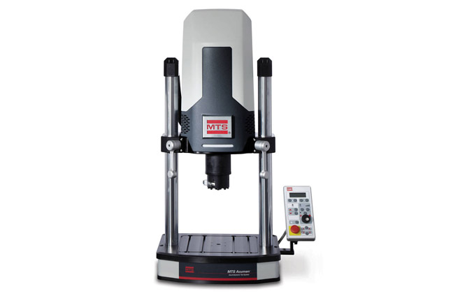
Acumen® Electrodynamic Test Systems
With force capacities up to 12kN or down to milli-Newtons, these clean and quiet systems can extend energy-efficient electrodynamic testing to many applications.
MTS Systems
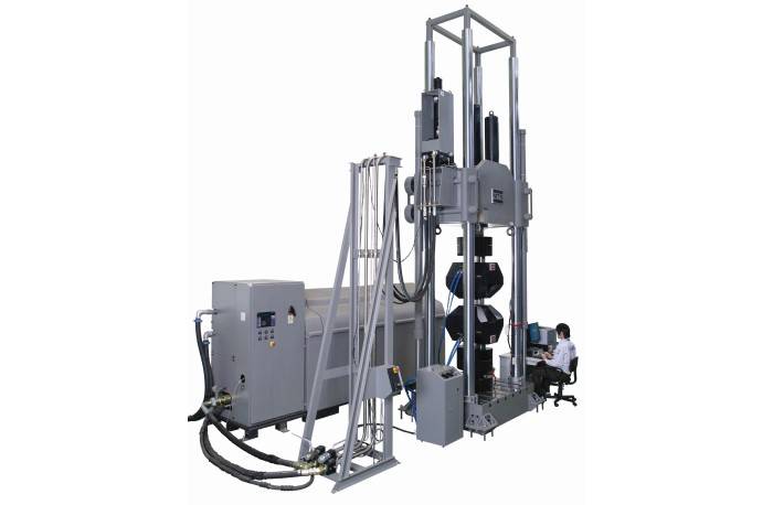
Ultra-stiff, four-column servohydraulic load frames, dynamically rated to deliver loads ranging from 1 to 30 MN. Higher capacity load frames and unique features can be custom engineered to order.
Test types
Test specimens
| 1. | Optional Tie Bar |
|---|---|
| 2. | High-Accuracy Linear Variable Differential Transducer (LVDT) |
| 3. | Precision-machined, ultra-stiff columns |
| 4. | Optional Hydraulic Crosshead Positioning Cylinders |
| 5. | High-Stiffness Crosshead - Integrated Actuator - Integrated Hydraulic Manifold - Close-coupled Accumulators |
| 6. | Optional Hose Stand |
| 7. | Hydraulic Service Manifold (HSM) - Optional hose stand-mounted - Optional crosshead-mounted (shown) - Optional floor-standing |
| 8. | Crosshead Lift/Lock Controls - Optional hose stand-mounted (shown) - Optional floor-standing |
| 9. | Optional Hydraulic Grip Supply |
| 10. | Load Frame Base Options - Standard T-Slot (shown) - Integrated Strong Floor |
| 11. | Precision Force Transducer - Base-mounted (shown) - Actuator-mounted |
| 12. | Optional High-Force Accessories - Compression Platens - Hydraulic Wedge Grips (shown) - Bend Fixtures - Custom Fixtures |
| 13. | Crosshead Clamping Mechanism |
| 14. | High-Performance MTS Actuator - Crosshead-mounted - High-Stiffness - Doubled-ended - Dynamically rated |
| Standard Models | Custom Models | ||||||||
|---|---|---|---|---|---|---|---|---|---|
| Load Frame Specifications | Units | 311.31 | 311.32 | 311.41 | 311.51 | 311.61 | 311.71 | 311.81 | 311.91 |
| Dynamic Force Ratings | kN | 1000 | 1200 | 2500 | 5000 | 7500 | 10,000 | 20,000 | 30,000 |
| (kip) | (220) | (265) | (550) | (1100) | (1650) | (2200) | (4400) | (6600) | |
| Standard Dynamic Strokes | mm | 150, 250 | 150, 250 | 150, 300 | 300 | Custom load frame dimensions vary according to customers' specific application requirements. Consult an MTS Applications Engineer for more information. | |||
| (in) | (6, 10) | (6, 10) | (6,12) | (12) | |||||
| Column Diameter | mm | 101.6 | 101.6 | 152.4 | 203.2 | ||||
| (in) | (4.00) | (4.00) | (6.00) | (8.00) | |||||
| Column Spacing ( width ) | mm | 711.2 | 711.2 | 762 | 1016.0 | ||||
| (in) | (28.0) | (28.0) | (30.0) | (40.0) | |||||
| Column Spacing ( depth ) | mm | 406.4 | 406.4 | 508.0 | 812.8 | ||||
| (in) | (16.0) | (16.0) | (20.0) | (32.0) | |||||
| Load Frame Height | mm | 2946-5486 | 2946-5486 | Note 3 | 4470-8534 | ||||
| (min-max) | (in) | (116-216) | (116-216) | Note 3 | (176-336) | ||||
| Specimen and Grip Spacing | mm | 254-2794 | 254-2794 | Note 2 | 450-4500 | ||||
| (min-max) | (in) | (10-110) | (10-110) | Note 2 | (17.8-177) | ||||
| Base Width ( width ) | mm | 914.4 | 914.4 | 1066.8 | 1422.4 | ||||
| (in) | (36.0) | (36.0) | (42.0) | (56.0) | |||||
| Base Width (including lifts) | mm | 1219 | 1219 | 1492.5 | 1903 | ||||
| (in) | (48.0) | (48.0) | (58.8) | (75.0) | |||||
| Base Depth | mm | 1016 | 1016 | 1168.4 | 1397 | ||||
| (in) | (40.0) | (40.0) | (46.0) | (55.0) | |||||
| Base Height ( from floor ) | mm | 280.9 | 280.9 | 332 | 450 | ||||
| (in) | (11.06) | (11.06) | (13.06) | (17.8) | |||||
| Hose Stand Spacing ( max ) | mm | 921 | 921 | 2479 | 2479 | ||||
| (in) | (36.3) | (36.3) | (97.7) | (97.7) | |||||
| Hose Stand Width | mm | 991 | 991 | 991 | 991 | ||||
| (in) | (39.0) | (39.0) | (39.0) | (39.0) | |||||
| Hose Stand Depth | mm | 688 | 688 | 688 | 688 | ||||
| (in) | (27.1) | (27.1) | (27.1) | (27.1) | |||||
| Hose Stand Height | mm | 2426 | 2426 | 2819 | 3200 | ||||
| (in) | (95.5) | (95.5) | (111.0) | (126.0) | |||||
| Approximate Crosshead Weight | kg | 1225 | 1225 | 2903 | 7938 | ||||
| (lb) | (2700) | (2700) | (6400) | (17,500) | |||||
| Approximate Total Weight | kg | 4100 | 4100 | 9525 | 21500 | ||||
| (lb) | (9100) | (9100) | (21,000) | (47,500) | |||||
| System Stiffness 4 | N/m | 1.6 X 10 9 | 1.6 X 10 9 | 3.1 X 10 9 | 3.9 X 10 9 | ||||
| lbf/in | 9.3 X 10 6 | 9.3 X 10 6 | 17.4 X 10 6 | 22.6 X 10 6 |
| 1.Model 311.31 & 311.32 with actuator retracted, 311.41 & 311.51 with actuator at mid-stroke |
|---|
| 2.Model 311.41 150 mm stroke is 400 – 3000 mm (15.75 – 118.1 in), 311.41 300 mm stroke is 400 – 3385 (13.31 – 133.3 in) |
| 3.Model 311.41 150 mm stroke is 3554 – 6154 (140.0 – 242.3 in), 311.41 300 mm stroke is 3720 – 6768 (146.5 – 266.5 in) |
| 4.Stiffness calculated at a crosshead height of 2 meters (78.7 inch) above the base. |
Specifications are taken from the official MTS product page and may change; please confirm with our team before ordering.
MTS Systems
With force capacities up to 12kN or down to milli-Newtons, these clean and quiet systems can extend energy-efficient electrodynamic testing to many applications.
MTS Systems
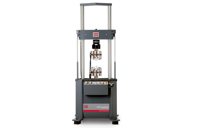
From complex thermomechanical fatigue studies to standard tension and compression tests, MTS Landmark systems deliver accurate, repeatable results.
MTS Systems
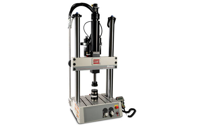
These servohydraulic test systems deliver the performance, versatility and accuracy required to properly characterize the dynamic and static properties of an extreme range of biomedical…
MTS Systems
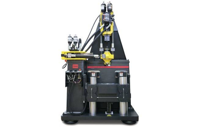
Apply precise single- or multi-axial linear and rotational forces to elastomeric materials and components to ensure quality and optimize performance and durability.