MTS Systems
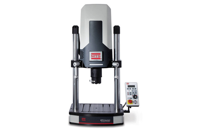
Acumen® Electrodynamic Test Systems
With force capacities up to 12kN or down to milli-Newtons, these clean and quiet systems can extend energy-efficient electrodynamic testing to many applications.
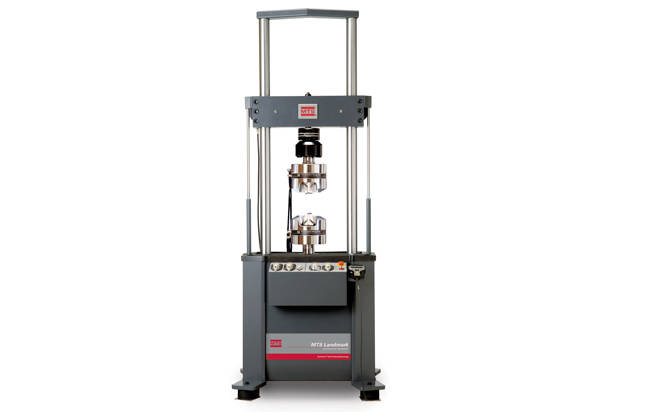
MTS Systems
From complex thermomechanical fatigue studies to standard tension and compression tests, MTS Landmark systems deliver accurate, repeatable results. Robustly manufactured with SureCoat® technology that extends actuator rod longevity 10x over conventionally chrome-plated rods, these systems will perform reliably for years.
Test types
Test specimens
Test standards
| LOAD FRAME | DIAGRAM | MODEL | ||||||
|---|---|---|---|---|---|---|---|---|
| SPECIFICATIONS¹ | DETAIL | UNITS | 370.10 | 370.25 | 370.50 | |||
| Actuator | Actuator | Actuator | Actuator | Actuator | Actuator | |||
| integral | integral to | integral | integral to | integral | integral to | |||
| to Base | Crosshead | to Base | Crosshead | to Base | Crosshead | |||
| Force capacity | kN | 100 | 100 | 250 | 250 | 500 | 500 | |
| (rated dynamic force) | (kip) | (22) | (22) | (55) | (55) | (110) | (110) | |
| Available actuator ratings₁ (nominal) | kN | 15, 25, 50, 100 | 15, 25, 50, 100 | 100, 250 | 100, 250 | 250, 500 | 250, 500 | |
| (kip) | (3.3, 5.5, 11, 22 ) | (3.3, 5.5, 11, 22 ) | (22, 55 ) | (22, 55 ) | (55, 110 ) | (55, 110 ) | ||
| Actuator dynamic stroke₁ | mm | 100, 150 , 250 | 100, 150 , 250 | 150 , 250 | 150 , 250 | 150 | 150 | |
| (in) | (4, 6 , 10) | (4, 6 , 10) | ( 6 , 10) | ( 6 , 10) | ( 6 ) | ( 6 ) | ||
| Min vertical test space - | A | mm | 140 | 70 | 231 | 159 | 427 | 345 |
| standard height₂ | (in) | (5.5) | (2.8) | (9.1) | (6.3) | (16.8) | (13.6) | |
| Max vertical test space - | A | mm | 1283 | 1213 | 1621 | 1549 | 2085 | 2002 |
| standard height₃ | (in) | (50.5) | (47.8) | (63.8) | (61.0) | (82.1) | (78.8) | |
| Min vertical test space - | A | mm | 363 | 292 | 485 | 413 | NA | NA |
| extended height₂ | (in) | (14.3) | (11.5) | (19.1) | (16.3) | NA | NA | |
| Max vertical test space - | A | mm | 1753 | 1683 | 2129 | 2058 | NA | NA |
| extended height₃ | (in) | (69.0) | (66.3) | (83.8) | (81.0) | NA | NA | |
| Working height₄ | B | mm | 922₈, ₁₅ | 922₁₅ | 922₈, ₁₅ | 922₁₅ | 922₁₅ | 922₁₅ |
| (in) | (36.3) | (36.3) | (36.3) | (36.3) | (36.3) | (36.3) | ||
| Column spacing | C | mm | 533 | 533 | 635 | 635 | 762 | 762 |
| (test space width) | (in) | (21.0) | (21.0) | (25.0) | (25.0) | (30.0) | (30.0) | |
| Column diameter | D | mm | 76.2 | 76.2 | 76.2 | 76.2 | 101.6 | 101.6 |
| (in) | (3.00) | (3.00) | (3.00) | (3.00) | (4.00) | (4.00) | ||
| Base width | E | mm | 1018 | 1018 | 1112 | 1112 | 1351 | 1351 |
| (in) | (40.1) | (40.1) | (43.8) | (43.8) | (53.2) | (53.2) | ||
| Base depth | F | mm | 698 | 698 | 737 | 737 | 896 | 896 |
| (in) | (27.5) | (27.5) | (29.0) | (29.0) | (35.3) | (35.3) | ||
| Diagonal clearance - | G | mm | 2580₈, ₁₁, ₁₅ | 2649₁₁, ₁₅ | 3084₈, ₁₁, ₁₅ | 3155₁₁, ₁₅ | 3629₁₁, ₁₅ | 3699₁₁, ₁₅ |
| standard height₅ | (in) | (101.6) | (104.3) | (121.4) | (124.2) | (142.9) | (145.6) | |
| Diagonal clearance - | G | mm | 3084₈, ₁₁, ₁₅ | 3153₁₁, ₁₅ | 3589₈, ₁₁, ₁₅ | 3660₁₁, ₁₅ | NA | NA |
| extended height₅ | (in) | (121.4) | (124.1) | (141.3) | (144.1) | NA | NA | |
| Overall height - | H | mm | 2588₈, ₁₂, ₁₅ | 3028₉, ₁₅ | 3095₈, ₁₄, ₁₅ | 3490₁₀, ₁₅ | 3688 | 3961 |
| standard height₆ | (in) | (101.9) | (119.2) | (121.8) | (137.4) | (145.2) | (155.9) | |
| Overall height - | H | N/m | 3058₈, ₁₃, ₁₅ | 3498₉, ₁₅ | 3603₈, ₁₄, ₁₅ | 3998₁₀, ₁₅ | NA | NA |
| extended height₆ | (in) | (120.4) | (137.7) | (141.8) | (157.4) | NA | NA | |
| Stiffness₇ | N/m | 467 x 10⁶ | 467 x 10⁶ | 473 x 10⁶ | 473 x 10⁶ | 777 x 10⁶ | 777 x 10⁶ | |
| (lbf/in) | (2.66 x 10⁶) | (2.66 x 10⁶) | (2.7 x 10⁶) | (2.7 x 10⁶) | (4.44 x 10⁶) | (4.44 x 10⁶) | ||
| Weight | kg | 635 | 820 | 875 | 1095 | 1570 | 1760 | |
| (lb) | (1400) | (1800) | (1925) | (2410) | (3455) | (3875) | ||
| 1.All load frame specifications listed in this chart are based upon the actuator ratings and dynamic stroke values indicated by bold text. | ||||||||
| 2. Min Vertical Test Space: Span between force transducer and piston rod face when fully retracted at beginning of the dynamic stroke; crosshead down, no alignment fixture. | ||||||||
| 3. Max Vertical Test Space: Span between force transducer and piston rod face when fully retracted at beginning of the dynamic stroke; crosshead up, no alignment fixture. | ||||||||
| 4. Working Height: Floor to top of work surface; includes standard FabCell isolation. | ||||||||
| 5. Diagonal Clearance: Column height (far side) to tip of foot with FabCell; tie bar or enclosure not included. | ||||||||
| 6. Overall Height: From floor, including standard FabCell isolation, to the highest point on crosshead; crosshead fully raised (most common stroke length). | ||||||||
| 7.Measured at typical testing height with hydraulic wedge grips and cylindrical dog-bone specimen. | ||||||||
| Typical testing heights per model: Model 370.10 = 750 mm (29.5 in); Model 370.25 = 900 mm (35.5 in); Model 370.50 = 1250 mm (49.2 in) | ||||||||
| 8.Add 178 mm (7 in) to dimensions B, G, & H for 250 mm (10 in) stroke actuators integral to base. | ||||||||
| 9.Add 229 mm (9 in) to dimension H for 250 mm (10 in) stroke actuators integral to crosshead. | ||||||||
| 10. Add 203 mm (8 in) to dimension H for 250 mm (10 in) stroke actuators integral to crosshead. | ||||||||
| 11. For frames with an optional tie bar add 51 mm (2 in) to dimension G. | ||||||||
| 12. For 370.10 frames with standard columns, optional tie bar and actuator integral to base add 14 mm (.53 in) to dimension H. | ||||||||
| 13. For 370.10 frames with extended columns, optional tie bar and actuator integral to base add 51 mm (2 in) to dimension H. | ||||||||
| 14. For 370.25 frames with standard or extended columns, optional tie bar and actuator integral to base add 14 mm (.53 in) to dimension H. | ||||||||
| 15. For load frames with optional pneumatic /elastomeric vibration isolation mounts, add 62 mm (2.44 in) to dimensions B, G, and H. |
| LOAD FRAME | DIAGRAM | MODEL | |
|---|---|---|---|
| SPECIFICATIONS 1 | DETAIL | UNITS | 370.10 200 Hz Elastomer |
| Force capacity | kN | 100 | |
| (rated dynamic force) | (kip) | (22) | |
| Available actuator ratings₁ (nominal) | kN | 15, 25 | |
| (kip) | (3.3, 5.5 ) | ||
| Actuator dynamic stroke₁ | mm | 100 | |
| (in) | (4) | ||
| Min vertical test space - | A | mm | 0 |
| standard height₂ | (in) | 0 | |
| Max vertical test space - | A | mm | 788 |
| standard height₃ | (in) | (31.0) | |
| Working height₄ | B | mm | 922 |
| (in) | (36.3) | ||
| Column spacing | C | mm | 533 |
| (test space width) | (in) | (21.0) | |
| Column diameter | D | mm | 76.2 |
| (in) | (3.00) | ||
| Base width | E | mm | 1018 |
| (in) | (40.1) | ||
| Base depth | F | mm | 698 |
| (in) | (27.5) | ||
| Diagonal clearance₅ | G | mm | 2079₈ |
| (in) | (81.8) | ||
| Overall height₆ | H | mm | 2065₉ |
| (in) | (81.3) | ||
| Stiffness₇ | N/m | 467 x 10⁶ | |
| (lb/in) | (2.66 x 10⁶) | ||
| Weight | kg | 635 | |
| (lb) | (1400) | ||
| 1.All load frame specifications listed in this chart are based upon the actuator ratings and dynamic stroke values indicated by bold text. | |||
| 2. Min Vertical Test Space: Span between force transducer and piston rod face when fully retracted at beginning of the dynamic stroke; crosshead down, no alignment fixture. | |||
| 3. Max Vertical Test Space: Span between force transducer and piston rod face when fully retracted at beginning of the dynamic stroke; crosshead up, no alignment fixture. | |||
| 4. Working Height: Floor to top of work surface; includes standard FabCell isolation. | |||
| 5. Diagonal Clearance: Column height (far side) to tip of foot with FabCell; tie bar or enclosure not included. | |||
| 6. Overall Height: From floor, including standard FabCell isolation, to the highest point on crosshead; crosshead fully raised (most common stroke length). | |||
| 7.Measured at crosshead height of 750 mm (29.5 in). | |||
| 8.For frames with an optional tie bar add 51 mm (2 in) to dimension G. | |||
| 9.For 370.10 200 Hz elastomer frames with an optional tie bar add 28 mm (1.1 in) to dimension H. |
| Tabletop Load Frame Specifications |
|---|
| Model 370.02 tabletop load frames are available standard or extended heights with the |
| actuator configured integral to load frame crosshead. |
| LOAD FRAME | DIAGRAM | MODEL | ||
|---|---|---|---|---|
| SPECIFICATIONS₁ | DETAIL | UNITS | 370.02 | 370.02 100 Hz Elastomer |
| Force capacity | kN | 25 | 25 | |
| (rated dynamic force) | (kip) | (5.5) | (5.5) | |
| Available actuator ratings₁ (nominal) | kN | 15 , 25 | 15 , 25 | |
| (kip) | ( 3.3 , 5.5) | ( 3.3 , 5.5) | ||
| Actuator dynamic stroke₁ | mm | 100 , 150 | 100 , 150 | |
| (in) | ( 4 , 6) | ( 4 , 6) | ||
| Min vertical test space - | A | mm | 144 | 144 |
| standard height₂ | (in) | (5.7) | (5.7) | |
| Max vertical test space - | A | mm | 827 | 827 |
| standard height₃ | (in) | (32.6) | (32.6) | |
| Min vertical test space - | A | mm | 398 | 398 |
| extended height₂ | (in) | (15.7) | (15.7) | |
| Max vertical test space - | A | mm | 1335 | 1335 |
| extended height₃ | (in) | (52.6) | (52.6) | |
| Working height₄ | B | mm | 230₈ | 230₈ |
| (in) | (9.1) | (9.1) | ||
| Column spacing | C | mm | 460 | 460 |
| (in) | (18.1) | (18.1) | ||
| Column diameter | D | mm | 76.2 | 76.2 |
| (test space width) | (in) | (3.00) | (3.00) | |
| Base width | E | mm | 622 | 622 |
| (in) | (24.5) | (24.5) | ||
| Base depth | F | mm | 577 | 577 |
| (in) | (22.7) | (22.7) | ||
| Diagonal clearance - | G | mm | 1750₈ | 1750₈ |
| standard height₅ | (in) | (68.9) | (68.9) | |
| Diagonal clearance - | G | mm | 2250₈ | 2250₈ |
| extended height₅ | (in) | (88.6) | (88.6) | |
| Overall height - | H | mm | 1989₈ | 1989₈ |
| standard height₆ | (in) | (78.3) | (78.3) | |
| Overall height - | H | mm | 2624₈ | 2624₈ |
| extended height₆ | (in) | (103.3) | (103.3) | |
| Stiffness₇ | N/m | 345 x 10⁶ | 345 x 10⁶ | |
| (lb/in) | (1.95 x 10⁶) | (1.95 x 10⁶) | ||
| Weight | kg | 248 | 286 | |
| (lb) | (547) | (630) | ||
| 1.All load frame specifications listed in this chart are based upon the actuator ratings and dynamic stroke values indicated by bold text. | ||||
| 2.Min Vertical Test Space: Span between force transducer and piston rod face when fully retracted at beginning of the dynamic stroke; crosshead down, no alignment fixture. | ||||
| 3.Max Vertical Test Space: Span between force transducer and piston rod face when fully retracted at beginning of the dynamic stroke; crosshead up, no alignment fixture. | ||||
| 4.Working Height: Floor to top of work surface; includes standard FabCell isolation. | ||||
| 5.Diagonal Clearance: Hose height to tip of foot with FabCell; crosshead down. | ||||
| 6.Overall Height: From floor, including standard FabCell isolation, to top of the hoses or highest point on actuator; crosshead fully raised. | ||||
| 7.Measured at crosshead height of 600 mm (23.6 in). | ||||
| 8.For load frames with optional pneumatic /elastomeric vibration isolation mounts, add 37 mm (1.44 in) to dimensions B, G, and H. |
Specifications are taken from the official MTS product page and may change; please confirm with our team before ordering.
MTS Systems
With force capacities up to 12kN or down to milli-Newtons, these clean and quiet systems can extend energy-efficient electrodynamic testing to many applications.
MTS Systems
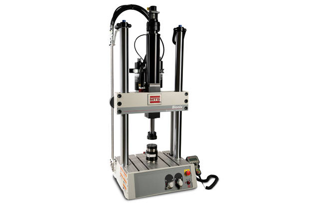
These servohydraulic test systems deliver the performance, versatility and accuracy required to properly characterize the dynamic and static properties of an extreme range of biomedical…
MTS Systems
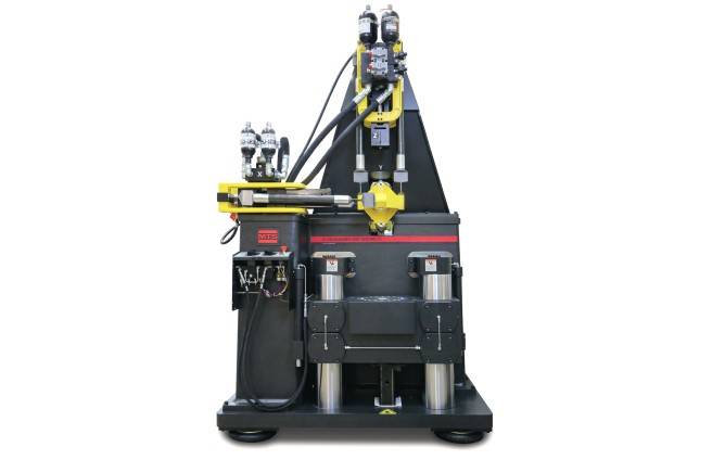
Apply precise single- or multi-axial linear and rotational forces to elastomeric materials and components to ensure quality and optimize performance and durability.
MTS Systems
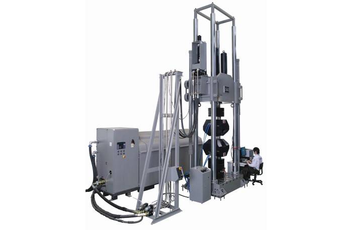
Ultra-stiff, four-column servohydraulic load frames, dynamically rated to deliver loads ranging from 1 to 30 MN.